3D Stair Calculator — Staircase Design Planner
Staircase — it's not just a functional element that connects the levels in the house, it is an important architectural part of any building, combining aspects of safety, comfort and aesthetics.
At the same time, designing a staircase requires a careful approach to calculating the dimensions, matching the optimal size of the construction elements in according with building rules and regulations.
In this article we will consider the key principles of calculation and design of stairs in view local building codes (US and UK), as well as provide recommendations on selecting the optimal parameters for different types of staircases.
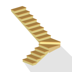
- Staircase Parts
- Staircase Types
- Staircase Design Principles
- Stair Angle (Slope/Pitch)
- Stairway Width
- Stairway Length (Number of Steps)
- Head Clearance
- Floor Opening Size
- Example Designing Staircase
- Structural Design Staircase
- Balustrade Requirements
- Building Codes and Regulations for Stairs
Anatomy Staircase — Stair Parts & Components Terminology
Constructionally, a staircase is made up of two main parts, which are found in all designs without exception. These are:
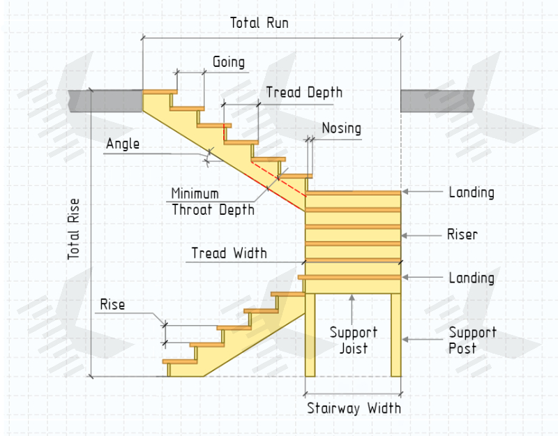
- Treads. These are horizontal parts on which the foot rests when going up or down the stairs.
- Stringers (Strings). Structural beams on which the treads are supported. Positioned at an angle to the floor surface and usually installed on either side of the staircase. Can be open or closed.
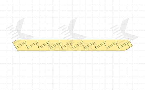
Closed Stringer (Housed/Routed/Side/Box), in professional terminology, is a solid beam to which the treads hidden behind the stringer. Treads are inserted into notches on the inner side or fixed on blocks or corners.
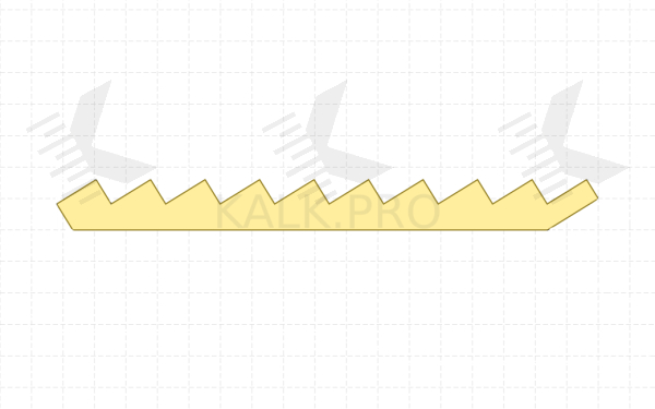
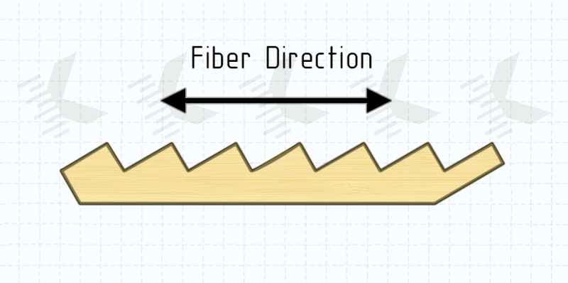
Open Stringer (Cut/Sawtooth) is so called because it has an angular cut or sawtooth shape. Treads are fixed to the horizontal surfaces of the stringer and are visible from the side.
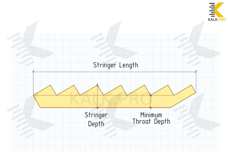
Another important difference. Minimum throat depth of an open stringer is decreased by sawcut depth, which generally reduces the load-bearing capacity.
There are also staircases with a combined stringers. In this construction, cut stringer is overlapped on the outside by a housed stringer. This makes the staircase more visually interesting and aesthetic, and also increases its load-bearing capacity.
At the same time, depending on the configuration and materials used, the staircase can also be contained additional parts and components, such as:
Step — is a common term for a two-part element: tread and riser.
- Risers. Vertical parts between the treads that form the back of each step.
- Landings. Horizontal platforms that form a turn between two stairways and used to change the direction of a stair, and serves as a resting place.
- Winder Steps (Winders). Triangular-trapezoidal shaped treads, narrower at one end and wider at the other. Used in turning staircases as an alternative to a landing.
- Support Joists. Structural rigidity elements connecting the supporting junctions and redistributing the load between them (not required in case of risers, as they duplicate the function).
- Support Posts. Vertical support posts installed under the stairs. Provides stability of the construction and serves as an additional contact point on the floor.
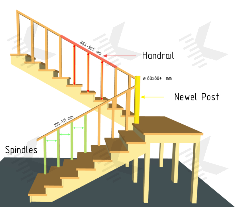
- Balustrade (Railing/Guarding). Includes balusters/spindles (vertical posts) and handrails (horizontal or repeating pitch support to be grasped by the hand).
In addition to these basic parts, it is important to know other staircase terms when designing. Be prepared to meet the following definitions:
- Rise (Step Height). Vertical distance from the top surface of the tread to the top surface of the following tread.
- Total Rise. Summary vertical height of the staircase from the ground floor level to floor second storey.
- Going (Run). Horizontal distance from the front edge any of tread to the front edge of the following tread.
- Total Run. Summary horizontal length of the staircase between the opposite sides (walls) stairwell.
- Tread Depth (Step Width). Horizontal distance from one edge of the tread to the other edge (along the narrow side). In difference to the going, step width also includes the overhang (nosing) and spacing under the riser, if riser is installed ON TOP the tread (if nosing and riser are missing, or riser is installed to the BACK the tread, tread depth = going).
- Tread Width (Step Length). Horizontal distance from one edge of the tread to the other edge (along the wide side). Length of the straight steps is equal to the stairway width (only true for open stringer stairs).
- Tread Overhang. It's mostly about nosing — horizontal distance of the front edge of the tread that extends beyond the riser or the vertical face of the step. At the same, tread overhang can also be on the side, it is a distance from edge to the vertical face of the stringer.
- Stair Angle (Slope). Angle between the stairway and the horizontal level (floor). Determines the steepness of the staircase. It is measured in degrees.
- Pitch. Ratio between the rise (step height) and going.
- Pitch Line. Notional line connecting the nosing of the treads within a single stairway. Angle between the pitch line and the horizontal level is also stair angle.
- Stairwell. This is the space allocated for the installation of a staircase. Includes the opening in the upper floor slab, the floor-to-floor height and the available area on the ground level.
- Stairway (Flight/March). An inclined staircase section that includes an uninterrupted series of steps between floors or landings (winders).
- Stairway Width. Horizontal distance between the outer edges of the stairway. In all cases, stairway width is equal to the straight tread length (excluding closed stringer staircases, because treads are installed inside the stringer).
- Walking line. The center line of the stairway, the most comfortable for movement.
Staircase Types
Choosing the staircase type for a house most often depends on individual preferences, available area and finances.
Stairs can be classified by different factors, including materials, rotation angle, turning design, number of flights, number of stringers, etc.
Below, let's look at the most common choices that can satisfy the needs of most users.
Staircases by Rotation Angle
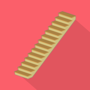
Straight Stairs. The simplest and common type of stairs. They have a rectilinear design without turns and narrow sections, going equal throughout. For walking the most comfortable. But at the same time are the most cumbersome stairs.
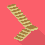
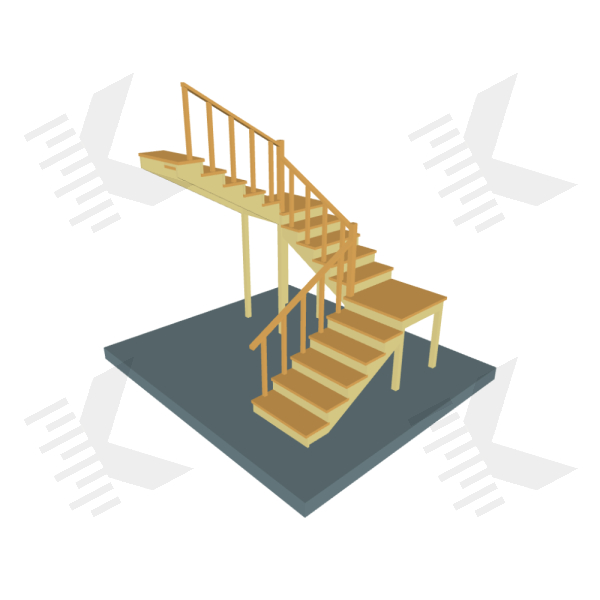
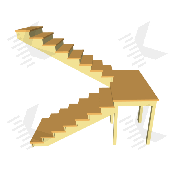
L-Shaped Stairs, 90° (Quarter-Turn Staircases). Consists of two straight stairways (as a rule, unequal in length), forming a turning of 90 degrees. The flights are connected by a landing or winder steps. Optimal choice, if the opening length is long enough, but does not allow you to put a straight staircase.
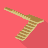
U-Shaped Stairs, 180° (Half-Turn Staircases, Switchback). Consists of two or three straight stairways that form one 180° turn or two 90° turns, respectively. Double flight staircases with a 180° turning are one of the most compact of all linear staircases. However, U-shaped stairs are more difficult to construct and a 180 turn itself is often less comfortable than other choices.
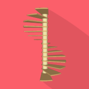
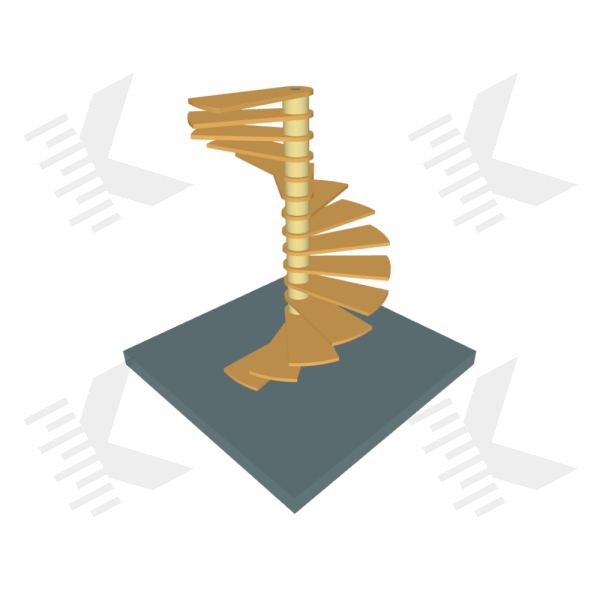
Spiral Stairs. Have a continuous circular shape and rotate around a center pole at 360 degrees or more, relative to entrance and exit. As compact as possible, but not as friendly for regular use.
Staircases by Turning Design
Straight Stairs with Landing. Includes one or more horizontal landings, that are used as a turning space between the stairways. This is the most successful design of a staircase with a turn, because on a wide landing two persons can freely move apart and it can be used as a resting place, which is especially important for the elderly and children.
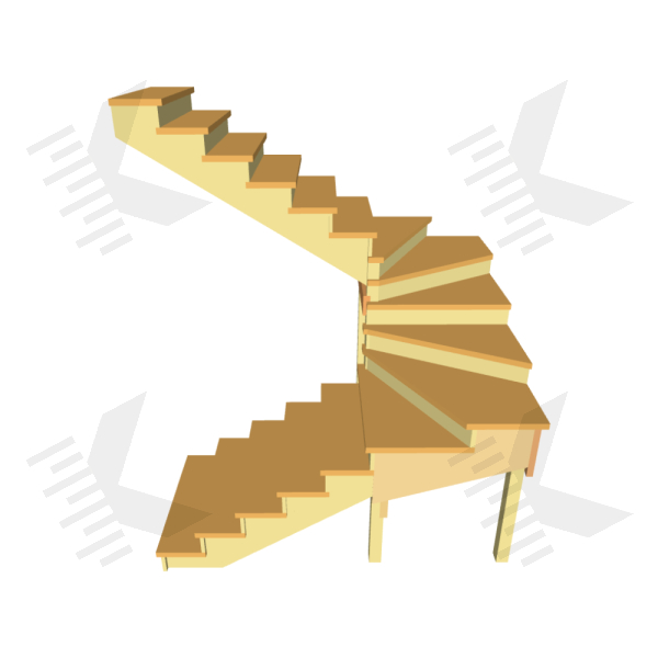
Winder Stairs. In this staircase design, the turning is smoother than the variant with a landing, this allows you to save the opening size even more. Unfortunately, turning section is not safe and does not allow two persons to move apart easily. In addition, such stairs are characterized by difficulty in design, manufacture and installation. Usually used in cases where the opening leaves no other choices.
Staircase Design Principles
Staircases should be designed to be as user-friendly as possible in the available opening (in many cases it is not expandable and has a limited size).
It is important to take into account the persons feature who will be using it. For example, if there are children or older in the house, stairs should be safe and comfortable for them in the first instance.
In the following we will focus on three documents: International Building Code 2021 (IBC), International Residential Code 2021 (IRC), UK Building Regulations 2010 (Approved Document B (Protection from falling, collision and impact), Approved Document K (Fire safety)).
Tread Size — Rise and Going
In the context fully calculation of staircase, knowledge of the tread size standards is important for designing. Since only the tread size will further establish whether the staircase is comfortable or not, and all other parameters will be «matched» to keep the tread size within the permitted value.
Let's look at what regulations contain.
- IBC (1011.5): rise range allow 4-7" (102-178 mm), going range allow 10-11” (254-279 mm);
- IRC (R311.7.5): rise shall be not more than 7¾" (196 mm), going shall be not more than 10” (254 mm);
- UK Building Regulations (Approved Document K, 1.2): rise 150-220 mm, going 223-300 mm.
IRC (R311.7.10.1): tread of the spiral staircases shall be identical and have a depth of not less than 6¾ inches (171 mm) at the walkline. Rise shall be not more than 9½ inches (241 mm).
As seen, in documents the range of values going is presented wide enough. Main recommendation for comfortable walking on stair, whole foot must stand on the tread.
By statistics, the largest common shoe size for men is: 13 US / 12 UK / 47 EUR (under ISO 19407). In this case, an average foot length a human will be around 300 mm. It is considered that a going of the same size is comfortable for both most men and women.
It is for this reason is most often use stair tread depth 270, 300 mm (11½”, 12”).
A going increase will may to trip over, because the rhythm is off. And conversely, if reduced going too much, it could take to increase the step height, which will require more forces when rising. But how do choose the correct step height?
Blondel Formula
French architect Jacques François Blondel researched the design of domestic architecture. In his book «Cours d'architecture», he established the basic principles of staircase design, which later became the «law».
Blondel found that tread depth and step height are proportional to the average length of a person's step. In this way, the formula appeared.
Blondel’s Formula. 2 × R + G = 600-650 mm (23.6-25.6 in)*
- R — rise;
- G — going;
- * — average step length.
This formula suggests the important fact — tread depth to height ratio 1 to 2.
Calculation by this formula is just a found of values and checking the condition for true. At the same it is important to follow that the ratio of going to rise should be 1:2 or as close to as possible.
Let's go back, as previously figured out, optimal tread width is 300 mm. Let's put this value into the formula. Then step height must be half the going — 150 mm.
2 × 150 + 300 = 600 mm (formula is true).
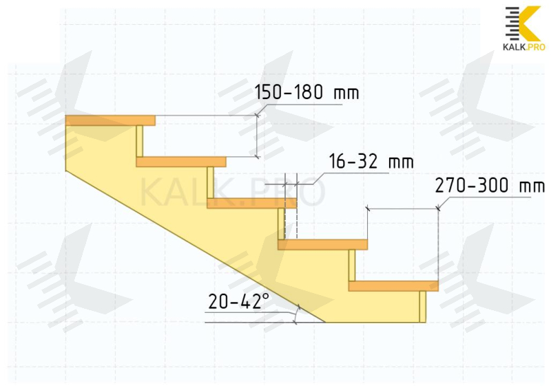
Also, Blondel calculated optimal step height and tread depth — 150-180 mm (6-7”) (R) and 270-300 mm (11½”-12”) (G), respectively. As seen not all values are correct by codes, but from a practical point of view are still comfortable.
Note, that it is not always possible to get into the optimal values. In this case, when choosing parameters of the steps, it is recommended to focus on the height of the person — for a higher man can be selected more higher step, which will increase the going, which is necessary for larger foot sizes. And conversely.
Do not forget about the assortment of lumber in stores. Most common stair treads/boards (Thickness/Height x Depth x Width/Length) in US: ½”-1¼” x 10”-12” x 36”-48”, in UK: 20-38 x 250-300 x 900-1500 mm.
Stair Nosing — Tread Overhang
Tread overhang is important for more comfortable movement and foot position when moving up or down, as it allows the tread to be deeper. Regulations strictly define the overhang size of the tread nose for design. Otherwise it may not be safe to walking on the stairs.
IBC (1011.5.5) defines the size of the leading edge of the treads, they shall overhang no more than 32 mm (1¼") beyond the tread below. Curvature and bevel shall also be determined - they shall not be less than 1.6 mm (1/16") but not more than 14 mm (9/16") from the leading edge of the tread.
Additionally, IRC R311.7.5.3 specifies that the overhang shall not be less than 19 mm (¾").
UK Regulations (AD K 1.7, 1.8) recommend avoid overlap on step nosing that protrude over tread below. If nosing overhang, ensure that they do not protrude more than 25 mm. At the same time, the overlap of the treads should be at least 16 mm.
Risers
Riser — is the vertical surface between the treads that forms the face of each step. Risers are used to create a beautiful visual line on the staircase. They give you the opportunity to add a touch of elegance and individual style to staircase, either by painting it to match the treads or by painting it in any other harmonious color.
Recommended that the risers be manufactured from the same type of wood as the treads.
Riser height specifications are regulated by the common rules for rise (height measured vertically between the nosings of adjacent treads).
IBC (1011.5.2). Riser heights shall be more than 7 inches (178 mm) and 4 inches (102 mm) minimum.
IRC (R311.7.5.1). Riser heights shall be not more than 7¾ inches (196 mm). The greatest riser height within any flight of stairs shall not exceed the smallest by more than ⅜ inch (9.5 mm).
UK Building Regulations (AD K, 1.2) — do not provide specific height notes for risers, there's only rise 150-220 mm.
Open risers are allowed, but not recommended as they reduce the safety of the staircase. Following IRC (R311.7.5.1) at open risers grade below shall not permit the passage of a 4 inch diameter (102 mm) sphere, or 100 mm under UK Building Regulations (AD K, 1.6).
Risers can be installed vertical or sloped from the underside of the nosing of the tread above at an angle not more than 30° from the vertical under IRC (R311.7.5.1).
It is important to note that the risers provide additional support and generally increase the load-capacity of the staircase on open stringers, because it allows increasing the cross-section of the beam.
Stair Angle — Stairway Slope, Pitch Line
Stair angle measures how steep or shallow a staircase is to be. If the angle is big, the stairs will be steep, and rather, if the angle is small, the stairs will be shallow.
Too steep a slope can make the stairs difficult to rise, especially for the elderly or people with disabilities. Too shallow a slope may make the stairs too long and uncomfortable to use, due to steps that are much low.
In general, stair angle is calculated through the mathematical formula for angle of a right triangle is calculated through the arctangent and cathetes. In case with staircase, cathetes being the «Total Rise» and «Total Run».
Stair angle formula: tan α = Total Rise / Total Run;
α = arctan (Total Rise / Total Run).
IBC, IRC do not specify the exact stair angle, there are only rise and going values. But it can be used, too.
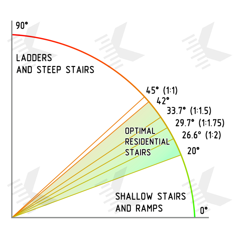
Only In UK Building Regulations noted of a maximum slope for private staircases — 42°.
It is important to note that the notional line that connects the nosing of the treads is called the pitch line. Within a single step, a pitch line is the hypotenuse of a right rectangle with sides «Rise» and «Going».
And since pitch line is generally a mirror of the projection of the stair slope line, then the formula can be used also in relation to pitch line.
tan α = R/G;
α = arctan (R/G)
- R — rise;
- G — going.
If the IBC step parameters are transferred from the previous paragraph to the formula, the resulting slopes:
- α = arctan (4/11) = 20.0° (min rise, max going);
- α = arctan (4/10) = 21.8° (min rise, min going);
- α = arctan (7/11) = 32.5° (max rise, max going);
- α = arctan (7/10) = 35.0° (max rise, min going).
For IRC:
- α = arctan (7¾/10) = 37.8°
For UK Building Regulations:
- α = arctan (150/300) = 26.6° (min rise, max going);
- α = arctan (150/223) = 33.9° (min rise, min going);
- α = arctan (220/300) = 36.3° (max rise, max going);
- α = arctan (220/223) = 44.6° (max rise, min going).
So, under the regulations, the permissible (optimal) angle of slope is in the range of 20-42°.
Pitch — its ratio length on horizontal to height on vertical in identical units, expressing steepness.
For calculating the pitch, need to divide rise and run of the structure by rise to get the ratio of length per unit of height. Expressed as a «1 in _» pitch (where a «1 in 1» equals 45°) is used.
For example, for a step height of 200 mm and a going of 300 mm, resulting in the proportion 200/300. If this expression is divided by 200, the resulting pitch is 1:1.5.
From a practical point of view, the most comfortable staircase would be with a pitch of 1:2, that equal angle 26.6°.
Stairway Width — Width of Flights of Stairs
Stairway Width are crucial in ensuring for accessibility, safety and efficient flow of foot traffic, also determines how many people can pass through it concurrently.
Depending on the number of people living in the house, the staircase should accommodate more people and facilitate swift evacuation in emergencies.
In addition, width of the stairway should allow for unobstructed movement of bulky stuff at the house.
Following IRC (R311.7.1), the width of stairways should be no less than 36 inches (914 mm) in at all points above the handrail and below the permitted headroom height. At and below the handrail height, the clear width of the stairway should be at least 31½ inches (787 mm) if a handrail is installed on one side, and 27 inches (698 mm) if handrails are installed on both sides.
For spiral stairways (R311.7.10.1) the clear width at and below the handrails shall be not less than 26 inch (660 mm) and the walkline radius shall be not greater than 24½ inch (622 mm).
IBC (1005.3.1): the capacity, in inches, of means of egress stairways shall be calculated by multiplying the occupant load served by such stairways by a means of egress capacity factor of 0.3 inch (7.6 mm) per occupant. Where stairways serve more than one story, only the occupant load of each story considered individually shall be used in calculating the required capacity of the stairways serving that story.
Occupant load factor for Residential — 200 gross.
IBC (1011.2): minimum stairway width shall be not less than 44 inch (1118 mm).
In UK Building Regulations (AD K, 1.11) written for stairs within the entrance storey of a dwelling, have flights with minimum clear widths of 900 mm.
For stairs that form part of means of escape additionally using Approved Document B Volume 1 (3.60): stairway should be at least 1100 mm wide. The width is the clear width between the walls or balustrades. Any handrails and strings intruding into that width by a maximum of 100 mm on each side may be ignored.
For single family residential for US, we recommend designing clear stairway width a 1118 mm (44 inch). With both sides handrails it's the equivalent of a 1219 mm (48 inch) board. Alternatively, can be used equivalent sizes for UK and other countries by local regulations: 1000 mm board on stairway with both handrails (at 900 mm for clear stairway).
Stairway Length and Vertical Rise — How Many Steps in a Flight of Stairs
Following IRC (R311.7.3) a flight of stairs shall not have a vertical rise greater than 3835 mm (12 ft 7 inch) between floor levels or landings, or under IBC (1011.8) — vertical rise 3658 mm (12 ft) maximum.
This would about equate to 20 code legal risers or steps to the stairs.
In UK Building Regulation (AD K, 1.3f) written, that in a tier that is uninterrupted by cross-gangways, and where the pitch exceeds 25°, use a maximum number of steps of 40. At the same time, in the paragraph 1.15 specified that, if stairs have more than 36 risers in consecutive flights, make a minimum of one change of direction between flights.
Also in the paragraph 1.14 state, that for flights between landings the number of risers should be a maximum of:
- institutional and assembly stairs – 16 risers;
- utility stairs – 16 risers;
- easy access stairs – 12 risers.
To summarize, for residential stairs we recommend installing 16-20 steps per flight and preferably no more, because a stair stringer that is too long will not have enough load capacity.
Headroom for Stairs — Minimum Head Clearance
Stairwell should be planned at the same time as the design of the staircase or, even better, at the stage of creating the house project. Stairwell should be wide and high enough to allow for comfortable access along the entire length of the staircase.
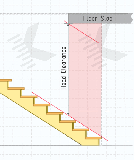
Stair Headroom — its vertical distance between the pitch line to the upper floor slab or upper stairway. Minimum headroom clearance important parameter, that helps to reduce the chance of bumping head or other injuries on stairways.
According to IRC (1011.3) и IRC (R311.7.2) headroom in stairways shall be not less than 6 feet 8 inches(2032 mm) for flight staircases. Spiral stairways are permitted a 78 inches (1981 mm) headroom clearance.
Following UK Building Regulations (AD K, 1.10) — on the access between levels, provide the minimum headroom 2000 mm. For loft conversions where there is not enough space to achieve 2000 mm headroom throughout stairway. Clearance can be sloped: decreasing from 2000 mm on one edge stairway to 1800 mm on the other edge (1900 mm in center of the stairway).
Floor Opening Size — How to Calculate?
If the opening width on the second floor is understandable (it is equal to the stairway width), then with the opening length everything is not so clear.
The length of the opening will depend on the minimum headroom clearance, which must be respected 2000 mm (or more) from the pitch line to the upper floor slab along the walkline. When this value cannot be respected, the slab shall be interrupted.
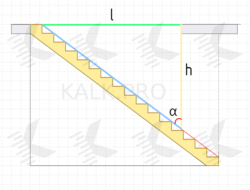
To calculate the opening length, we need to use trigonometric functions. In general, we again must calculate the cathetate of a right triangle.
Suppose the slope of the stair — 26.6°, minimum headroom should be equal to 2000 mm, upper floor slab thickness we will take equal to 200 mm.
Then the opening length on the second floor will be equal to:
l = h / tan α = (2000 + 200) / 0.88 ≈ 2500 mm.
If the opening of the second floor is designed to be equal to the stair length, this calculation can be skipped.
Example Designing Staircase — Stair Calculation
After we have estimated which parameters of the staircase are optimal. Consider the situation when the house is not yet built, and we are just developing a house project in which we need to designing of the stairwell and calculate its dimensions.
In residential buildings usually is floor-to-floor height 3000 mm (10 ft), suppose we have this. In this case staircase height of the will also be 3000 mm (if top step at the level of 2nd floor level).
Straight Stair Calculation
Let's assume that we are going to build a straight staircase, with stairway width of 1000 mm (39⅜ inch).
So, by now we have already known the two sizes of the stairwell: width and height. Then to find out the dimension’s stairwell, we need to calculate the stair length.
Let's try to consider enough common step 150x300 mm (≈ 6x12 inch), where the 1st is Step Height and the 2nd is Tread Depth.
At a stairwell height of 3000 mm and a step height of 150 mm, it will be possible to install 20 whole straight treads:
3000 mm / 150 mm = 20 treads.
At 20 treads width of 300 mm, the staircase length will be equal to 6000 mm:
20 treads × 300 mm = 6000 mm.
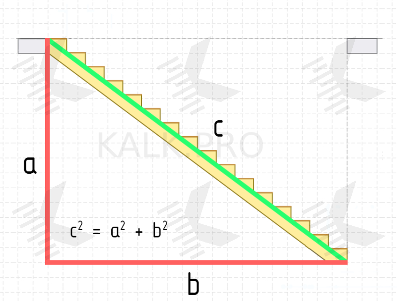
In this case, according to the Pythagoras theorem, stringer beam length will be equal to:
с2 = а2 (length) + b2 (height) ≈ 6708 mm.
In this situation is important that beams of this length are not available to buying. Manufacturing companies do not produce them, as they will not have sufficient load capacity. More often than not, stores will offer a 2400/3600/4200 mm (94/142/165 inch) long beams, at most you can find custom-made 5000 mm beams.
Let's try to designing an optimal staircase from the reverse.
Take as a condition that the length of the stringer will be maximum, equal to 5000 mm. Then the stair length, following the Pythagoras theorem, will be 4000 mm. Recall, that by condition the stair height is 3000 mm.
Can at once check the stair angle by the formula «arctan α = Total Rise / Total Run», then we get a value of 36.87° (slope is true).
Now we have to choose the steps size and their quantity.
If we further consider a 300 mm wide tread, the calculations show that it is not possible to insert the whole number of treads: 4000 mm / 300 mm = 13.33 treads.
In this case it is needed to use 13 treads and cut the stringer, or to add 14th tread and to cut all the treads in width. Anyway, the step height will be from 214 mm to 231 mm (with 14 and 13 steps, respectively). Which is still a large for the average person. Remind that according to Blondel, the optimal rise is around 150-180 mm.
Next, let's try to take a tread with a depth of 250 mm. In this case, we will be able to install 16 whole treads (4000 mm / 250 mm = 16 treads). Step height will be 187.5 mm, which is almost optimal according to Blondel and the IRC/UK rules are followed.
Please keep this staircase design in mind, we will come back to it when we start calculating stair loads.
Calculation Stair with Landing
The previous showed the «perfect» situation when it is possible to create a stairwell of the required size at the planning stage of the house. But this is rarely the case.
Usually, the house is already built and there is a finished stairwell, the dimensions of which cannot be changed. Moreover, often this opening is very limited in size.
In such a situation, in the existing stairwell tries to install staircase in decreasing order of comfort:
Straight -> L-shaped -> U-shaped, or
Straight -> with Landing -> with Winders.
Let's consider the example of a single flight staircase, when there is a stairwell 3500 mm run, 3000 mm rise, 1000 mm wide.
In this case, the angle of slope will be tan α = 3000 mm / 3500 mm = 40.6°.
This angle is not valid under IRC and IBC rules, but is allowed under UK rules. Generally, this is enough steep stair, not exactly comfortable for the elderly and children. Straight stairs don't suit for us.
So, let's continue and try to put a 180° U-shaped double flight staircase with landing in a similar opening (only it'll be a wider opening): length 3500 mm, height 3000 mm, width 2000 mm.
Assume, stairway width will be 1000 mm and the landing depth will be equal to the stairway width. The landing is located in the mid-height of the staircase. Therefore, the length (in horizontal projection) of the upper and lower flight will be 2500 mm each (expected equal number of steps for each flight)
Landing height will be equal to the step height.
First, estimate the number of steps, using a tread depth of 300 mm and a height of 150 mm.
For each flight of length 2500 mm, there will be 9 whole treads: 2500 / 300 mm = 8.33 ≈ 9 treads.
The step height (taking into account the landing) will be calculated using the equation: 3000 mm / (9 × 2 + 1) ≈ 158 mm.
In checking the step comfort using Blondel's formula, we can see that this is true:
158 × 2 + 300 = 600-650 mm.
Also, in this case, the angle of slope will be:
tan α = (9 × 158) / (3500 - 1000) = 29.63°.
What's very comfortable to move up and down the stairs.
Calculation Winder Stairs
To reduce the length of the stairwell even further, instead of an intermediate landing, often installing winder treads.
The main feature of these treads is triangular-trapezoidal shape: their depth decreases from the outer edge to the inner edge. At that, comfortable movement is possible only in the center of the tread or on the outer side adjacent to the wall; on the inner side, movement is impossible.
Designing a turning section with winders is doing by different graphical methods, but all of them are based on the proportional widening of the ends of the winder treads at the expense of the width of the straight treads.
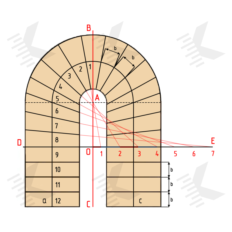
Let’s consider one method, using the example of a U-shaped staircase (with a 180° turn).
In the middle of the planned flights is drawn a walking line, which must be closed with a semicircle centered on point «A». Along the resulting line of walking line «abc», mark the winder and straight treads with a width of «b» at the intersection. The marking of the treads starts from the upper and in such a way that the vertical line «BC» divides its width into two equal parts.
At the next stage, the size of the winders must be corrected. For this it is recommended to select the three nearest adjacent straight treads (for smoother turning, it may be possible to include a large number of treads) and along the outer edge of the last to draw a horizontal line «DE».
Tread lines «1» and «2» continue in the direction of line «DE» (intersecting at point «A») and getting walking line segment «1-2» (equal to «b»). Then on the line «OE» marks points with intervals equal to «b», taking into account the point «A» in the center of the turning. First tread at the point «1» will be distant from point «O» by a distance «b/2», and all next points will be distant from each other by a distance «b».
Number of points on the «OE» line depends on the number of winders to be corrected.
After that, the points on the line «OE» are connected to the relevant points along the walking line, resulting in the diagram with winders of the correct shape.
Similar operations need to be repeated with to the opposite half.
Structural Design Staircase — Load Tests, Stairway Deflection
Basis of load capacity calculation for stairs consists of determining the maximum load and deflection that the support beams can load-carrying without deformation or destruction. Let's understand the terms in more detail.
- Loads — forces or other actions that result from the weight of building materials, occupants and their possessions, environmental effects, differential movement and restrained dimensional changes.
Loads are forces that act on a structure. Loads can be categorized into two broad types: Dead Loads and Live Loads.
- Dead Load — static loads that remain relatively constant over time. Include loads from self-weight and other fixed structural elements.
- Live Load — variable loads produced by the use and occupancy of the building or other structure (such as from people or moving furniture).
Loads can be classified according to their intensity to point loads and distributed loads.
- Distributed Load — load, that has spread over a certain area or along a certain distance. It can be uniformly and variable.
- Uniform Distributed Load (UDL) — linear load, which has the same intensity along its entire path of application.
- Point Load (PL) — concentrated load applied at a specific point.
Finally, it should be considered the term «Deflection».
- Deflection — movement of the beam from its initial position by forces and loads applied to the element. For example, L/360 means that the deflection of the beam under load is limited to 1/360th of the span. For understanding, a «beam» with a length of 360 mm can deflect by a maximum of 1 mm.
Load requirements for stairs are specified in IBC and IRC for the US and in EN 1991: Actions on structures for UK.
Table 1607.1 in IBC specifies the minimum uniformly distributed live loads and minimum concentrated live loads requirements. For one- and two-family stairs minimum uniform load 40 PSF or equivalent concentrated load 300 lb. For other stairs minimum 100 PSF and 300 lb, respectively.
Table 1604.3 contain details lists deflection limits for floors — live load deflection limit is L/360, the total load deflection limit is L/240.
Similar requirements can be seen in the IRC. Table R301.5 contains minimum uniformly distributed live loads. Table R301.7 — allowable deflection of structural members.
EN 1991-1-1: Eurocode 1: Actions on structures, Table 6.2 there are requirements imposed loads on stairs in buildings. Uniformly distributed load — 2.0 kN/m2 to 4.0 kN/m2 and concentrated load — 2.0 kN to 4.0 kN.
EN 1995-1-1: Eurocode 5: Design of timber structures, Table 7.2 contain limiting values for deflections of beams on two supports — L/150 to L/300.
Stair Stringer Load Test
A detailed theoretical scientific basis for load calculations can be found in «Structural Analysis» by Aslam Kassimali; «Mechanics of Materials» by Ferdinand Beer, Jr. Johnston, E. Russell, John DeWolf, David Mazurek; «Mechanics of Materials» by James M. Gere, Barry J. Goodno; «Shigley's Mechanical Engineering Design» by Richard Budynas, Keith Nisbett.
Correct loads calculation is a very difficult process, that only experts can perform. There are many rules of mechanics of materials must be taken into account: the type of beam fixation (simply supported, cantilever, fixed-fixed, etc); how the load is spread along the length of the beam (distributed or concentrated); is fixed (restrained from motion) or free to move in each direction; as well as many different other conditions for loadings.
For easy the calculation, we will assume that all loads will be o uniform distributed (UDL) and beam simply supported at the ends. These simplifications will not affect the result globally, but will allow to check the beam yourself.
In terms of the sources above, the beam should be tested for deflection and the bending stress.
Deflection formula: f = (5 × w × L4) / (384 × E × I)
- w – distributed loads, N/m2 (lb/ft2);
- L – span length, m (ft);
- E – elastic modulus, Pa (psi);
- I – area moment of inertia (second moment of area), m4.
*deflection at Midspan
Bending stress formula: σ = (M × c) / I
- M – bending moment, N·m;
- c — central axis to the outermost fiber in the bending plane of the rectangle, m;
- I – area moment of Inertia (second moment of area), m4.
Let's consider a case of a double stringer straight staircase with parameters: length 4000 mm (total run), height 3000 mm (total rise), width 1000 mm (stairway width).
Stringer Length
One of the first things to start with is to correct calculate the length of the stringer. This is the easiest stage.
By Pythagoras' theorem, the length of the stringer will be:
с2 = а2 (length) + b2 (height) ≈ 5000 mm.
This value is the span length (L) in the basic formula above.
Will calculate the stair angle at once, this value will come in useful later.
tan α = Total Rise / Total Run;
α = arctan (Total Rise / Total Run) ≈ 36.87°.
Total Load — Calculation the Loads on a Beam
As an example, consider a traditional closed stair stringer, i.e., a solid beam to which the treads are inserted into notches on the inner side or fixed on blocks or corners.
To estimate the total load of the stringers, first calculating the dead load, i.e., the self-weight parts of the staircase.
Let's calculate the self-weight of the stringers (2 pcs). Beam length is known — 5000 mm, width and thickness are not.
To do this, it is better to check the lumber company assortment and see what is available. Such length only beam with dimensions 50x300x5000 mm (Depth x Width x Length).
Also, suppose we are working with pine, then the density of the wood will be around 350-850 kg/m3. Note, because of the calculating loads (are force), must be used unit weight (specific weight), not density. And to find the specific weight, we would need to multiply the density by the acceleration of free fall (standard gravity) g = 9.80665 m/s2.
But due to the fact that the density of pine is rather inaccurate value, for convenience of calculation, let's skip these calculations and take the unit weight of pine more rounded — 5000 N/m3.
In the following, we will also assume that all wood elements made of pine.
Then, to find the weight of the stringers needed to perform calculations:
Wood volume (single string): 5000 mm × 300 mm × 50 mm = 75,000,000 mm3 or 0.075 m3.
Wood volume (double string): 0.075 m3 × 2 pcs = 0.15 m3.
Total weight of the stringers: 5000 N/m3 × 0.15 m3 = 750 N.
Similarly, let's calculate the treads. From the calculation at the beginning of the article, we found out that with a staircase length of 4000 mm (total run) and a height of 3000 mm (total rise), there will be 16 treads.
Then tread depth will be equal to:
Total Run (4000 mm) / 16 treads = 250 mm.
Tread length (board length) is known to us, it equals stairway width minus the double thickness of the stringer, i.e., 1000 mm - (2 × 50 mm) = 900 mm, tread depth (board width) has just been calculated = 250mm. It is left to select the tread thickness (board height).
Since it is planned to build a staircase on two stringers, it is better to select a thicker board, for example, a typical 38 mm (1 1/2") stair tread.
So then, the total weight of the treads will be as follows:
Wood volume (single tread): 900 mm × 250 mm × 38 mm = 8,550,000 mm3 = 0.00855 m3.
Wood volume (all treads): 0.00855 m3 × 16 pcs = 0.1368 m3.
Total weight of the treads: 5000 N/m3 × 0.1368 m3 = 684 N.
Next, it's needed to calculate the riser’s weight. Calculation is fully similar to the treads.
Riser length (board length) is equal to the tread length = 900 mm. Riser depth (board width) is equal step height = (assuming that the tread is installed at the back):
Total Rise (3000 mm) / 16 treads = 187.5 mm;
Regarding to the riser thickness, it is better to select a thinner board, a typical 10 mm riser is usually used.
Therefore, the total weight of the risers will be:
Wood volume (single riser): 900 mm × 187.5 mm × 10 mm = 1,687,500 mm3 = 0.0016875 m3.
Wood volume (all risers): 0.0016875 m3 × 16 pcs = 0.027 m3.
Total weight of the risers: 5000 N/m3 × 0.027 m3 = 135 N.
It is also necessary to roughly estimate the weight of the balustrade. If to take a handrail size with 70x70 mm of square cross-section and 5000 mm length (handrail length is roughly equal to the stringer length) and 41x41 mm spindles with 900 mm height (number of balusters equals the number of steps), the weight of the balustrade will be:
Wood volume (handrail): 5000 mm × 70 mm × 70 mm = 24,500,000 mm3 = 0.0245 m3.
Wood volume (baluster): 900 mm × 41 mm × 41 mm = 1,512,900 mm3 = 0.0015129 m3.
Wood volume (balusters): 0.0015129 m3 × 16 pcs = 0.0242064 m3.
Total weight of the guarding: 5000 N/m3 × (0.0245 m3 + 0.0242064 m3) ≈ 244 N.
If necessary, it is still needed to add the weight of the carpet for the stairs. But we will do it as roughly as possible — will assume that the weight of the carpet is 15 N/m2 (≈ 1.5 kg/m2).
Carpeting area (treads): 250 mm (tread depth) × 900 mm (tread length) × 16 pcs = 3.6 m2.
Carpeting area (risers): 187.5 mm (riser depth) × 900 mm (tread length) × 16 pcs = 2.7 m2.
Total weight of the carpeting: (3.6 m2 + 2.7 m2) × 15 N/m2 ≈ 95 N.
Now it is possible to calculate the total dead load on the stair. This will help to find the uniform distributed load (UDL), i.e., load per unit length.
To begin, let's sum all the loads.
Total dead load: 750 N + 684 N + 135 N + 244 N + 95 N = 1908 N.
So, the linear dead load on a 5000 mm (5 m) beams will be:
1908 N / 5 m ≈ 382 N/m.
Before that, we only calculated dead loads, now additionally, its need to add live loads.
According to IBC (Table 1607.1) and IRC (Table R301.5) minimum uniformly distributed live loads for residential stairs is 40 PSF (equivalent to 1915 N/m2). For UK requirements in EN 1991-1-1 (Eurocode 1: Actions on structures, Table 6.2) — minimum uniformly distributed load 2000 N/m2.
The unit of the UDL is N/m for line loads and N/m2 for area loads.
As can be seen, the documents specify the unit in area load. To continue the calculation, it is needed to convert linear unit to a base (area unit).
To do this, multiply the linear load by the width of the impact. In our case, stair width is 1 m, so 1 N/m of line load will be equal to 1 N/m2 of area load.
Continue summing up the loads. Let's add 2000 N/m2 of live loads to the dead loads. Then the total UDL will be equal to:
382 N/m2 + 2000 N/m2 = 2382 N/m2.
It is important to note here. Since we are calculating inclined beams, the horizontal load per 1 m2 is multiplied by the cosine of the angle, which results it to the load of 1 m2 of the slope plan.
2382 N/m2 × cos(36.87°) ≈ 1906 N/m2.
And accordingly, because there are double stringers in our staircase, the load should be divided in half. Total load on one beam:
1906 N/m2 / 2 pcs = 953 N/m2.
Deflection Test — Beam Deflection Formulas
Deflection, in structural engineering terms, refers to the movement of a beam or node from its original position due to the forces and loads being applied to the member. It is also known as displacement and can occur from externally applied loads or from the weight of the structure itself, and the force of gravity to which this applies.
Remember, we are testing a 50x300x5000 mm beam (Width x Depth x Length).
Deflection formula: f = (5 × w × l4) / (384 × E × I)
- w – distributed loads, N/m2;
- L – span length, m;
- E – elastic modulus (Young's Modulus), N/m2;
- I – area moment of Inertia (second moment of area), m4.
Modulus of Elasticity for pine ≈ 10 GPA = 10,000,000,000 N/m2.
Area Moment of Inertia of rectangle formula: I = (b × h3) / 12
- b – width beam, m;
- h – depth (height) beam, m.
I = (0.05 × 0.33) / 12 = 0.0001125 m4.
And then the final deflection formula:
f = (5 × 953 × 54) / (384 × 10000000000 × 0,0001125) = 2978125 / 432000000 ≈ 0.007 m.
IBC (Table 1604.3) and similarly in IRC contain details lists deflection limits for floors — live load deflection limit is L/360, the total load deflection limit is L/240.
EN 1995-1-1: Eurocode 5: Design of timber structures, Table 7.2 contain limiting values for deflections of beams on two supports — L/150 to L/300.
Let's check the allowable minimum and maximum deflections value:
5 m / 360 ≈ 0.014 m;
5 m / 150 ≈ 0.033 m.
0.007 < 0.014;
0.007 < 0.033.
Deflection test passed.
Flexural Strength Test — Bending Stress Formulas
Failure in bending will occur when the bending moment is sufficient to induce tensile/compressive stresses greater than the yield stress of the material throughout the entire cross-section.
Flexural strength (bending stress) formula: σ = (M × c) / I = M / Z
- M – bending moment, N·m;
- c — central axis to the outermost fiber in the bending plane of the rectangle, m;
- I – area moment of Inertia (second moment of area), m4;
- Z — elastic section modulus (defined as Z = I / c), m3.
Bending moment formula: M = (w × L2) / 8
- w – distributed loads, N/m2;
- L – span length, m.
M = (953 × 52) / 8 ≈ 2978 N·m.
Section modulus of formula: Z = I / c
- c — central axis to the outermost fiber in the bending plane of the rectangle, m;
- I – area moment of Inertia (second moment of area), m4.
Centroidal distance formula: c = ½ × h
- h – depth (height) beam, m.
c = ½ × 0.3 = 0.15 m.
Area moment of Inertia of rectangle formula: I = (b × h3) / 12
- b – width beam, m;
- h – depth (height) beam, m.
I = (0.05 × 0.33) / 12 = 0.0001125 m4.
Then the final section modulus equation:
Z = 0.0001125 / 0.15 = 0.00075 m3.
Or directly for rectangle cross-sectional shape.
Section modulus of rectangle formula: Z = (b × h2) / 6
- b – width beam, m;
- h – depth (height) beam, m.
Z = (0.05 × 0.32) / 6 = 0.00075 m3.
Then final maximum bending stress formula:
σ = 2978 / 0.00075 ≈ 3,970,667 N/m2.
σ = 2978 × 0.15 / 0.0001125 ≈ 3,970,667 N/m2.
Average flexural strength for pine = 40 MPa = 40,000,000 N/m2.
3,970,667 < 40,000,000
Bending stress test passed.
Minimum Throat Depth Stringer
Now consider the situation when instead of a closed stringer will be used an open stringer. Let's assume that the beam has the same size 5000x300x50, where 300 mm is the depth of the beam.
For a cut stringer it is important to calculate the minimum throat depth of the stringer, i.e., depth that will remain after cutting the top of the beam for the landing places for the treads.
For this purpose, it is needed to find the bisector of the right triangle according to the known cathetes: tread depth — 250 mm, step height — 187.5 mm.
Right angled triangle formula: f = √2 × ((a × b) / (a + b))
f = √2 × ((250 × 187.5) / (250 + 187.5)) ≈ 152 mm.
Then from the total depth of the beam should be excluded 152 mm, as a result the minimum throat depth of the beam: 300 mm - 152 mm = 148 mm.
After that it is important to carry out the load analysis for the open stringer using the scheme above.
Stair Tread Load Test
Stair treads should be strong and secure enough to ensure safe movement. Therefore, for treads as well as for stringers, it is important to perform strength testing.
Tread load testing is fully identical to the calculations for the stringer beam, with the only exception. The treads are positioned in the horizontal plane, so thus no vertical loads are applied and therefore no additional slope corrections need to be introduced.
As an example, consider the tread we choose at the beginning of the calculations — 900x250x38 mm.
As we have already found out earlier, according to IBC, IRC and EN requirements the structural elements of the staircase must be able stress — UDL 2000 N/m2.
Since the single tread weight will be too insignificant, let's ignore it.
Then it is needed to calculate the surface area of the tread, so that we can estimate the loads correctly.
900 × 250 = 225000 mm2 = 0.225 m2.
Let's convert the normative load 2000 N/m2, to the tread area of 0.225 m2:
2000 × 0.225 = 450 N/m2.
And so, after that we can be start testing.
Deflection test:
f = (5 × 450 × 0.94) / (384 × 10,000,000,000 × 0.00000114) = 1476.225 / 4377600 ≈ 0.00034 m.
Area moment of Inertia: I = (0.25 × 0.0383) / 12 = 0.00000114 m4.
Table 1604.3 in IBC (table R301.7 in IRC) deflection limits for floor members — L/360.
Let's check the allowable deflection value:
0.9 m / 360 = 0.0025 m.
0.00034 < 0.0025;
Deflection test passed.
Bending stress test:
Flexural strength (bending stress): σ = M / Z = 46 / 0.00006 ≈ 766,667 N/m2.
Bending moment: M = (450 × 0.92) / 8 ≈ 46 N·m.
Section modulus: Z = (0.25 × 0.0382) / 6 ≈ 0.00006 m3.
Average flexural strength for pine = 40 MPa = 40,000,000 N/m2.
Bending stress test passed.
Balustrade — Handrail Height and Spindles Spacing
An important part of staircases is the railing (balustrade). Stair guards serve to prevent falls and provide support during rising and falling. It structurally contains support posts, balusters and handrails.
Under IBC (1014.2) and IRC (R311.7.8.1) handrail height, measured vertically from the sloped plane adjoining the tread nosing, or finish surface of ramp slope, shall be not less than 34 inches (864 mm) and not more than 38 inches (965 mm). According to UK Building Regulations (Approved Document K, Diagram 16) for single family dwellings stairs — 900 mm for all elements.
As for baluster spacing, many masters focus on the universal "4-inch sphere" rule and that's not exactly right. If to check IBC (1015.4 Opening limitations) or IRC (R312.1.3), there are other tolerances. Spindles on railings can be wider apart, up to 4 3/8 inches (111 mm) on the open side of stairs. In addition, the gap between the railing and the tread can accommodate a sphere up to 6 inches in diameter for the triangular openings at the open side of a stair, formed by the riser, tread and bottom rail of a guard.
The UK Building Regulations (Approved Document K, 3.3) specify a single value for all cases — a space of no more than 100 mm.
Another important, yet invisible function of the balustrade is to increase the rigidity and strength reserve of the staircase. Structurally, the balustrade is the stair framing, that distributes the load throughout the different components.
Stairs Code & Requirements
When designing a staircase, it is important to follow the relevant requirements and standards that regulate the tread sizes, guarding specification, allowable load-bearing on the structural elements, and other rules that help to ensure safe operation.
According to the building country: United States, United Kingdom, Australia, Canada, India... we recommend that you refer exactly to the local codes. But in general, the US and UK documents are suitable for most situation and can be referenced if there is no similar local building codes.
Sources
- International Building Code 2021 (IBC);
- International Residential Code 2021 (IRC);
- Occupational Safety and Health Administration (OSHA);
Building Code of Australia (BCA);
National Building Code of India (NBC);
- UK Building Regulations 2010 — Approved Document B (Protection from falling, collision and impact);
- UK Building Regulations 2010 — Approved Document K (Fire safety);
- EN 1991 (Eurocode 1) — Actions on structures;
- EN 1995 (Eurocode 5) — Design of timber structures;
- BS 5395-1:2010 — Stairs. Code of practice for the design of stairs with straight stairs and winders;
- BS 585-1:1989 — Wood stairs. Specification for stairs with closed risers for domestic use, including straight and winder flights and quarter or half landings;
- AS 1684 — Residential Timber Framed Construction;
- ISO 19407:2023 — Footwear. Sizing. Conversion of sizing systems;
- «Structural Analysis» by Aslam Kassimali;
- «Mechanics of Materials» by Ferdinand Beer, Jr. Johnston, E. Russell, John DeWolf, David Mazurek;
- «Mechanics of Materials» by James M. Gere, Barry J. Goodno;
- «Shigley's Mechanical Engineering Design» by Richard Budynas, Keith Nisbett;
- «Cours d'architecture» by Jacques François Blondel.
